
Sand Concentrator - Urethane Trommel Suspension System (1991)
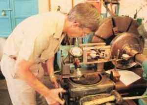
Fig 1. Performing a simulation on a 1/10-scale model using a special test setup on a lathe.
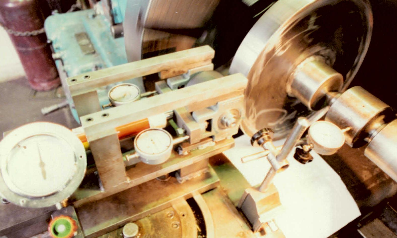
Fig 2. The test rig.
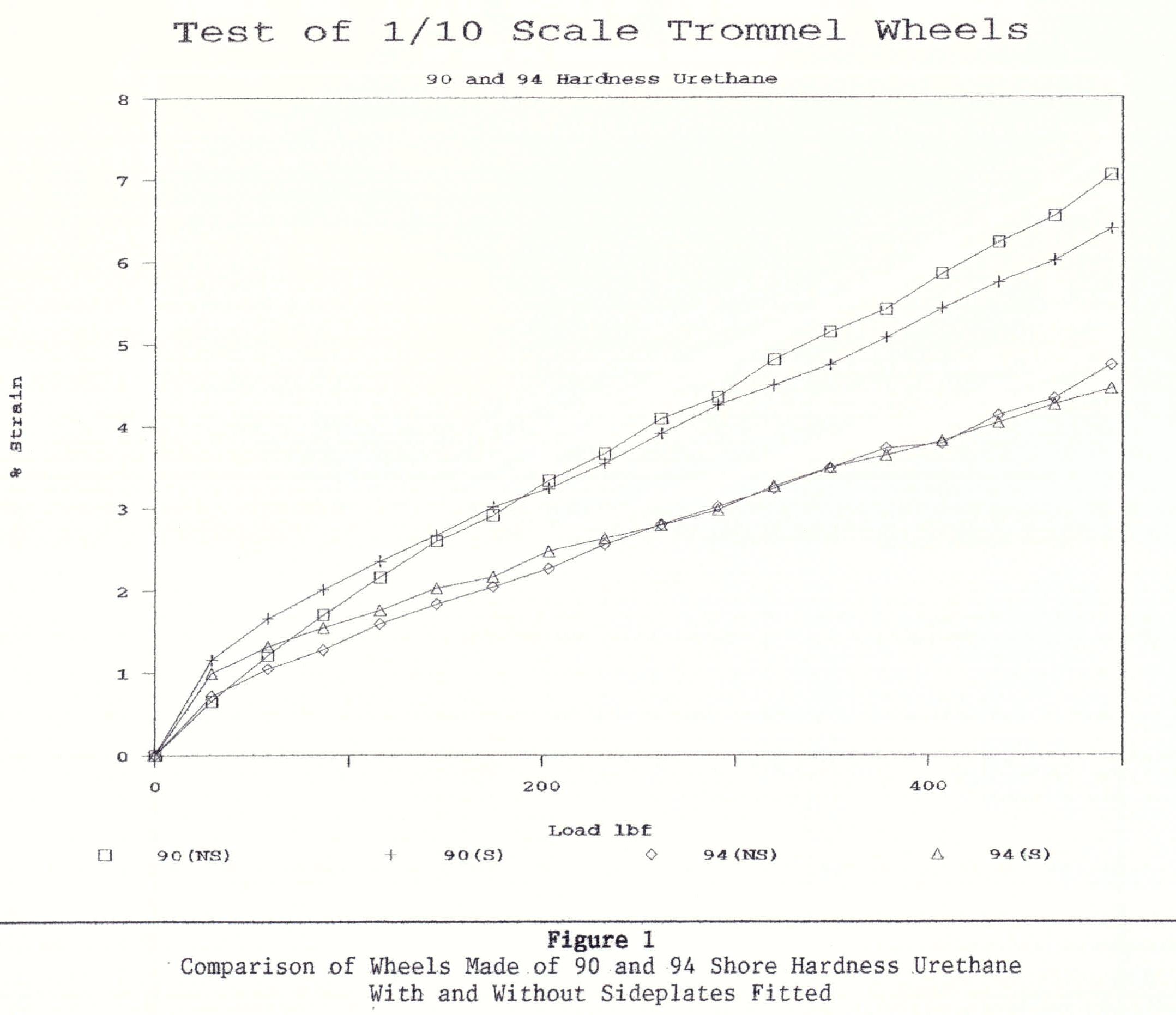
Fig 3. Shore 90 and 94 hardness with and without side plates.
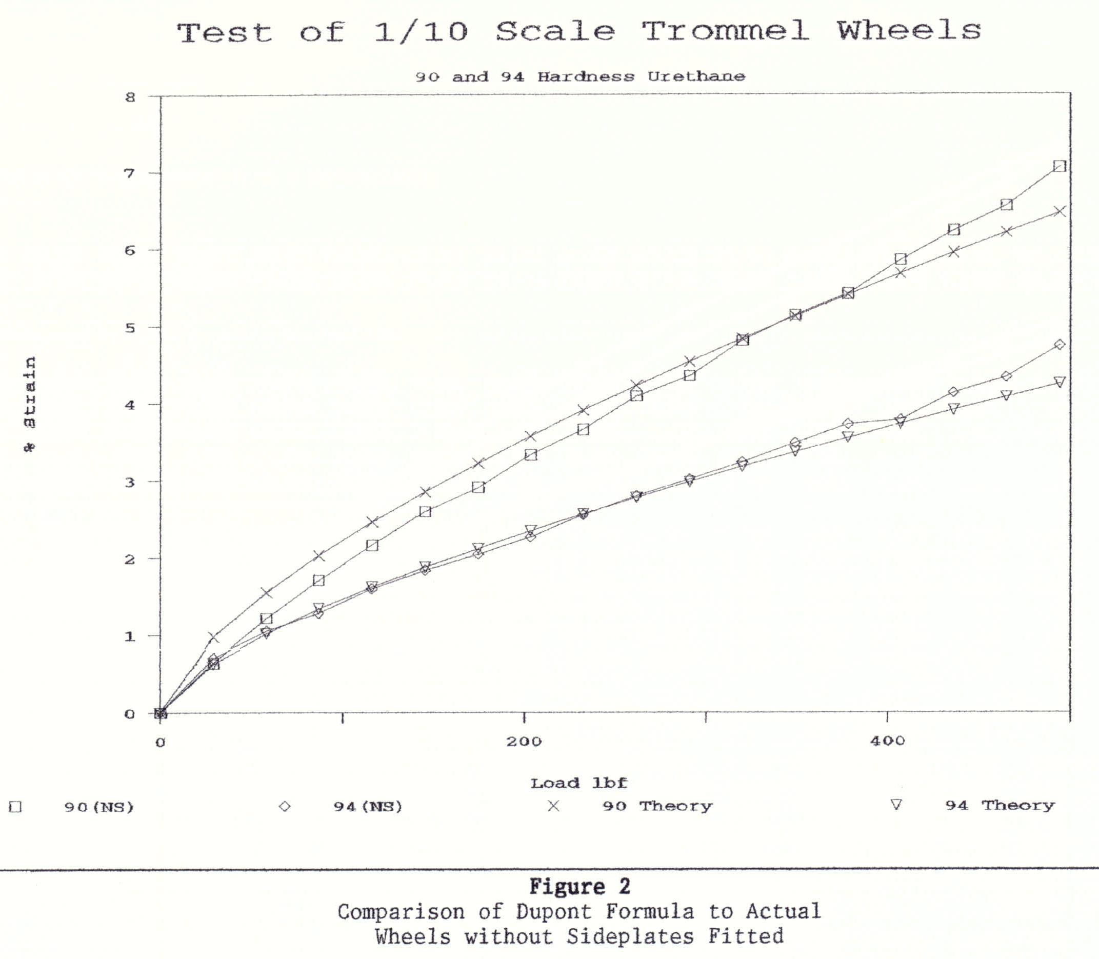
Fig 4. Theoretical compared to actual 90 and 94 shore hardness.
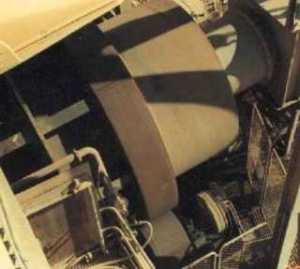
Fig 5. View of the top end of a trommel. Note the large riding ring running on the urethane wheel below.
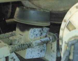
Fig 6. New trommel suspension system based on a urethane pinion wheel supported on a Lucas Gas-Hydraulics System.
Background
My first job as a civilian engineer, after leaving the Army in 1990, was as the Engineering Superintendent of Consolidated Rutile's operation on North Stradbroke Island. Soon after arriving there, problems developed with the two trommels on the Bayside and Gordon Concentrators.
A trommel is a large, rotating cylinder that contains an array of sieves in its wall. At CRL, these cylinders were around 3.4 metres in diameter and sat on four large steel wheels that rotated, thereby causing the trommel to rotate. Alluvium from the dredge entered the top of the trommel and, as the trommel rotated, the alluvium fell through the holes in the sieves to land in the header tank of a large floating concentration plant. At the top and the bottom of the trommel were large, 50mm-thick mild steel riding rings which sat on the steel wheels. In order for the alluvium to pass down the trommel, the trommel was inclined, and to keep the trommel in position on the rotating wheels, the wheels were canted so that the trommel was being driven uphill. Unfortunately, this design involved a lot of scrubbing of metal surfaces such that the riding rings lost around 6mm of thickness each year. When the thickness of the riding ring had decreased from its original 50mm to around 19mm, the ring began to flex, and this resulted in the welds of the webs inside the ring failing with a complete collapse of the trommel. It was therefore necessary, every 6 years or so, to change out the trommels. This was a very costly operation, necessitating the plant to be shut down for a number of weeks. The concentrator had to be dragged to the flat bank of sand that had to be constructed, and a large crane had to be brought in from the mainland. Additionally, the replacement trommel had to be constructed and carried to the site. This was a huge engineering exercise and, in the end, would typically cost millions of dollars.
The Idea of Using Urethane instead of Steel
I came up with the idea of using polyurethane instead of steel for the driving wheels. This would greatly reduce the pressure on the riding rings and would also virtually eliminate wear.
50.6% of CRL was owned by a company called Cudgen RZ. 50.6% of Cudgen RZ was owned by Richards Bay of South Africa. Through this means, the South Africans effectively controlled CRL and had a window into the intimate workings of the Australian sand-mining industry. When I suggested using urethane instead of steel, the South African engineers said it was impossible. They had tried this idea before, and it had failed. CRL's Mainland Engineering department joined in the chorus.
The Mining Manager, Graham Jacques, asked me if I could somehow prove that I was right, say, by building a scale model. He didn't like Mainland Engineering interfering in the island's operations, and he had already seen that, on a number of occasions, my team and I had been able to do things that the Mainland Engineering group thought couldn't be done. For example, with the help of John Flynn, an extremely competent fitter (and a very pleasant person to work with), I had managed to eliminate the need for the use of a gear box in an intermediate pump moving water from the Kounpee trench up into the mining pond. I also had successfully installed pinion wheels at the base of the trommels to hold them in position rather than canting the driving wheels which, up to that time, had been the practice. Before I went to do that, I had been told it had been tried before and had failed. I proceeded with it anyway, confident it would work... and it did! So I said that I could build a scale model and, through a process called dimensional similitude, I could prove beyond any reasonable doubt that the idea was practical. In actuality, my focus would be on simply determining if the distortion of the urethane could be kept within a certain tolerance. It was known that if urethane did not distort beyond 10%, they would survive for an extended period of time. If the distortion was less than 5%, they would last indefinitely. My goal then was to design wheels that would have a distortion less than 5% and which I could keep cool. In that manner, I would arrive at a solution that would have a very low chance of ever failing.
Building a Scale Model
With helpful suggestions from Des Gerber, the manager of the Dunwich Workshop, and John Flynn, my foreman, a test rig was constructed that allowed me to test the model wheels on a lathe. Figure 2 shows the test rig. The urethane wheel was pressed against a large wheel held and rotated in the lathe. The large wheel was a 1/10-scale model of the riding ring of the trommel. As I wound in the slide on the lathe, the force being applied was measured by a hydraulic ram pressing on the yoke in which the model wheel was held. The deflection of the wheel was measured by a dial gauge. This allowed me to construct graphs of the loading force versus the deflection for various wheels. The width of contact of a full-sized wheel was 485mm. The diameter of a full-sized wheel rim was 600mm, with the outer diameter being 906mm. The load each full-sized wheel had to carry, when fully loaded, was 18,000 kg. This meant that the test rig wheel had to be loaded to 495 lbs to achieve the same loading conditions.
Readings of Lismore made four wheels for me using urethane of 90 and 94 shore hardness. Two wheels, one with 90 and the other with 94 shore hardness, were fitted with side plates. The other two were without side plates. The idea of the side plates was to examine what happened to the urethane if side expansion was restricted. In the end, it was found that the side plates were not necessary to reduce the distortion of the urethane. Before proceeding with the test, I gave the Mining Manager, Graham Jacques, a graph of the expected deformation. After the tests, I overlaid the test results on the graph. They matched almost precisely. Graham Jacques was delighted because, as previously, he loved to prove the Mainland Engineering Group wrong.
Because the testing verified that the formulae accurately described the deformation of the urethane under load, I was given the approval to proceed with the construction of full-sized wheels. Unfortunately, at that time, the White South African Government capitulated to international pressure and dropped Apartheid. The consequence of that was that South African sand miners were allowed to trade internationally. Their first act was to dump a quarter of a million tonnes of titanium slag on the world markets, and that put all Australian sand miners out of business for three years. Mining on North Stradbroke ceased, and I had to go find another job. A case of paradise lost!
Avoiding Failure Conditions
Keeping it Cool. Urethane will fail if it becomes hot. Urethane is a poor conductor of heat. If you've ever squished a ball between your fingers over and over again, it becomes warm. A rotating urethane wheel, constantly being distorted, will become warm also, and there is the possibility of the temperature rising to the point where the urethane's ability to sustain the load disappears. In that state, the urethane will fail. I therefore ensured that, as part of the design, the urethane wheels would be washed with filtered, cold water from the pond. This would have an additional effect of lubricating the urethane as well as washing away any grit. The effect of this was that the wear would be minimised as well. As it turned out, the wheels ran for around 15 years and no more wear occurred.
Preventing a "Flat Spot". Like all elastomers, under a load, urethane will creep and keep its set. In other words, if the trommel stopped, a "flat spot" would form. When the wheels started moving again, when the trommel riding rim hit the flat spot, the urethane would be under tremendous force, and it would rapidly develop stress cracks. To prevent that, I organised that Lucas provide me with air-driven rams that would immediately inflate if the trommel ever stopped moving. These rams were deliberately driven by compressed air stored in tanks such that no power was needed to raise the trommel off its wheels in the event of a power blackout or other similar mishap.
Adhesion of the Urethane Tyre to the Rim. Readings of Lismore cast the tyres onto the rims. Before they did that, I asked that the very coarse Whitworth-like thread be turned on each rim. The form of a Whitworth thread is radiused, and this ensures there is no stress build-up at the vertices and the valleys of the thread. The thread was deliberately angled at 45 degrees. This ensured that the stress was directly parallel to the shear line under compression. This gave the glue the greatest chance of adhesion. The extra surface area presented by the thread also played a part in ensuring the tyre never lifted off the rim.
Successful Beyond All Expectations
After a 3-year hiatus, the mining operation did start up again, and when it did, it was with the new wheels on the trommels. The wear of the driving wheels and the riding rings was virtually eliminated and, as a consequence, these wheels operated for around 15 years without failure. The cost of building and installing the wheels and pinion suspension system came to around $60,000. The idea saved around 1.5 million dollars every 6 years for the two concentrators operating at Gordon and Bayside. Over the 15-year period, the cost saving was in the order of 9 million dollars.
Occasionally, engineers ring me and ask me to tell them how I did it. Evidently, people are still trying and just can't seem to get it right!